For side slope leachate extraction applications, GunnCo provides pumps and pump systems as detailed in Section 2 of this catalog. The following application notes are for side slope systems, although they may relate to other applications. Additional application notes are provided in the pump sections.
PUMP SIZING/Basic Sump and Riser Design Considerations
Pumps should be selected based upon flow rate, sump area, and minimum and maximum system head conditions.
Pumps should be selected with accumulation and operation in mind. For instance, if the calculated average flow into the cell is 5 GPM, the sump might be sized to accumulate enough liquid to allow the pump to operate 20 minutes to 4 hours. A 40 to 60 GPM pump would be able to empty 24 hours of accumulated liquid in under 3 hours and the pump would be capable of keeping up with peak flow conditions. The sump area should always be sized to prevent the pump from short cycling with a minimum cycle time between pump starts of 20 minutes. Many sump designs require the pump to operate only a few times per day during wet conditions. We suggest sizing the sump for normal pump operation of a few hours per day and using the liquid level allowed to remain on the liner as a safety reserve for peak rain conditions. An undersized pump will run continuously and an oversized pump may short cycle, both resulting in a shortened pump life.
The riser pipe should be the minimum size noted on the pump curve/data sheets. This will ensure the pump will fit if the pipe loses some shape and will allow for use of exit fittings. Smaller riser sizes may be used but could affect pump placement (turning the slope at the toe of the riser) or the use of side exit fittings. For long pumps, larger riser pipes, multiple miter cuts, or an increasing pipe size or transition at the toe may be required.
The riser pipe may be extended in the horizontal direction to provide a free flowing sump area. Adequate riser perforations and composite drainage materials are essential to allow proper flow to the riser pipe pump sump area. The pump only needs to travel to the horizontal position just past the toe in most cases.
PUMP SIZING/Basic Force Main Design Considerations
Pump head conditions are determined not by the pump but by the piping system and elevations. The pump should be specified for the static lift plus friction losses of the piping system including the discharge pipe or hose. It is difficult to predict the exact piping system losses for a landfill. The best approach is to estimate the minimum and maximum head conditions and select a pump which will operate at both.
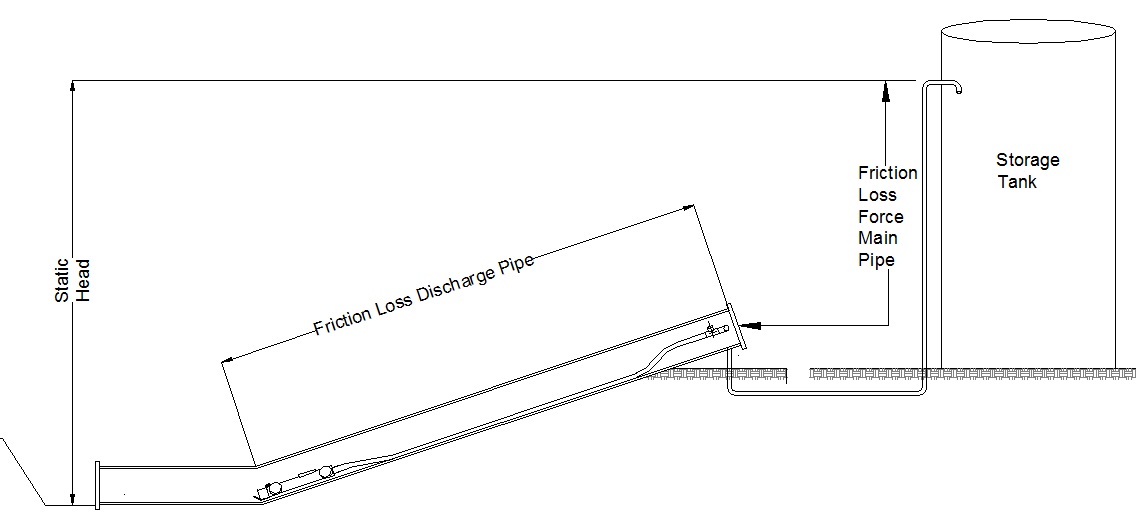
A problem in many landfills is the operation of multiple pumps into a common force main. This is a difficult application due to the unpredictable sequence of operation and often unknown or changing piping design. Often force mains are sized to maximum velocities and maximum pressure drops. This may cause the furthest pump from the force main discharge to require an extremely high discharge pressure when all pumps are operating, but a very low pressure when it is the only pump operating. In order for a pump to provide good service, it must be capable of operating at both points or have some means of flow control.
Small force main piping may be used to maintain high velocities (typically 7 fps) to minimize sedimentation and installation costs; however, once the pumps stop, the velocity becomes "0" and the solids settle. An oversized force main may minimize head variations but may allow the solids to settle until the velocity increases or the force main is cleaned by mechanical means such as an inducted high flow. A good approach is to size the force main to minimize pressure drops by increasing pipe size as the number of pumps increases.
If an appropriate pump or piping design is not available, methods such as flow orifices, pressure control valves, and flow switches and motor monitoring devices may be used. These are available from GunnCo upon request.
PUMP SELECTION/P2K and P3K Pumps
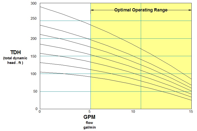
The P2K pumps offer the widest selection of flows and heads but must be carefully sized to operate within the published performance curve ranges. These pumps are available for single phase and three phase applications and meet most needs. Higher head versions of all models are available upon request.
The P3K wide performance range pumps are provided only in three phase versions for side slope duty and are limited to 1 and 2 horsepower models. These pumps offer excellent service where high solids (silt and sand) or scaling is present. They are a good choice for sites with wide pressure variations when multiple pumps are used.
MATERIALS OF CONSTRUCTION
The P2K Series pumps are available in 304 stainless steel or can be provided in 316 stainless steel for particularly corrosive applications. The preferred material of pump construction is 304 stainless steel with bearings in Teflon material. Buna rubber is available upon request and is used in abrasive applications where there is a lot of sand and abrasives in the leachate stream or where Teflon is not required.
The P3K Series are available in 316 stainless steel materials and in cast iron/stainless steel. These pumps are fitted in less corrosive applications such as containment area sumps or valve vaults.
P3KH Series are designed specifically for light SLURRIES or leachate streams where a lot of sand, silt, and solids may settle in the sump. These pumps may be used in side slope risers and also are well suited for truck load sumps other vertical sumps where solids may settle.
DISCHARGE PIPE and HOSE
Use of HDPE pipe provides low cost, and the pipe handles high pressure and ensures the pump is positioned in the same place each time it services. Flexible hose may be used where needed but should be limited to short risers of 50 feet or less in most cases. We prefer a vacuum rated EDPM hose for most applications.
VALVES AND ACCESSORIES
Check valves and isolation valves should be provided in all installations. Other items that may be required include air release/vacuum release valves, flow meters, pressure gauges, and sample valves. These are available from GunnCo upon request.
INSTALLATION
A key ingredient of a successful project completion is proper installation of the pump system. Considerations of the system installation should include:
-
Proper installation of the Riser Pipe per pipe manufacturers guidelines. This will ensure the heavy riser pipe remains in place and remains straight without slipping down the slope, which can affect pump placement and damage head walls where applicable. An upper flange should be used that will allow complete sealing of the pipe. A heavy backing ring is generally not required as they are designed to operate at full rated pipe pressure of 100 PSI +. The gas produced in the cell has been observed to be well under 5 PSI therefore most installation can be sealed using a flange and blind flange using 8 or 10 bolts( in the size range of 3/8” to 5/8”). If needed, additional bolts or gasket material can be added in future if determined necessary. Hardware should be stainless steel - galvanized hardware will eventually corrode and may be difficult and expensive to remove. The riser should extend above final grade to allow at least 12” between grade and the bottom of the riser flange but less than 24” is suggested. A riser too low may result in a portion of the riser being silted in or sediment run off entering collection system and if higher may make access difficult when servicing pump.
-
Recording the “AS BUILT” dimensions of the installed riser pipe. The pump must be properly located within the riser, and this information is recorded. This is historical information that may be needed in future-we suggest this information be noted in several locations including inside the control panel.
-
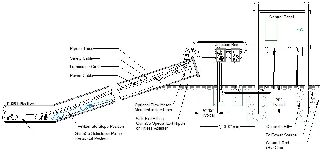
An accessible Pump Disconnect fitting for the pump discharge. The fitting should be placed by considering the weight of the pump and full pipe, being sure that placement will allow clearance for the pump to pass the fittings and sealing of the riser, and the connection must also meet strength and durability for the life of the landfill. We generally recommend use of a riser side discharge exit fitting located about 6” below the riser flange and positioned at 9:00, 12:00, or 3:00 position when possible.
-
The connection at 6:00 position is acceptable keeping in mind the pump may not roll over the disconnect fittings and will have to be lifted and maneuvered over the fitting. This may require more effort for large pumps. In all cases the fitting within the riser should not extend more than about 3” into the ID to allow ample space for the pump to roll past. An alternate arrangement we often see on system designs is having the discharge piping going through the front blind flange. This is acceptable, but again the weight of the pump/pipe assembly should be considered and means of removal of the flange from the piping needs to be provided for pump removal.
-
Proper selection, installation, and location of the discharge piping disconnect fitting is essential to allow future maintenance. Use of HDPE pipe and strictly stainless steel fittings is a must. Do not attempt to use unions to compensate for misalignment as flanges may assure a better seal.
-
Locate valves in proper sequence (to isolate cell pump and allow access to check valve or flow meter, etc.) and allow ample access around the valves and fittings for future service should replacement be needed.
-
Coordination is required between the piping contractor and the pump installer to ensure the required materials are provided and the pipes are located as needed to a clean connection.
-
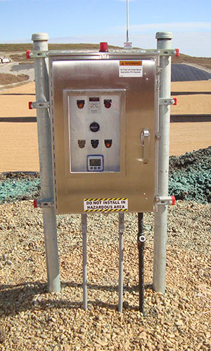
Properly mount control panel (and junction boxes). The control panel must be mounted at a safe distance from potentially hazardous sources of gas that might be ignited by the control panel relays or contactors. Rule of thumb is at least 10’ from the nearest riser. We do not recommend installing the control panel inside a riser house. The control panel will have a heater and thermostat to maintain heat and control condensation so mounting outside is OK.
-
The control panel should be mounted on a structure of sufficient rigidity to handle the weight of the control panel and any wind or snow/ice loads. The panel should be mounted at the correct level above final grade for average operator to see all indicators near eye level. There should be a flat and dry area of about 3’ minimum immediately in front of the panel for safe operator access and the panel should be easily accessible to encourage the operator to check status and allow safe service. Conduits and junction boxes (sometimes referred to as Break Out boxes) should be installed as required to protect the cables from damage (foot traffic, rodents, birds) while allowing recovery for service or replacement. This also ensures a gas tight seal for the control panel. Permanent sealing should not be used on pump power, transducer, and flow meter CABLES between risers and junction boxes. The junction boxes allow for permanent potting seals (seal offs) between the junction boxes and the control panel.
-
Junction boxes should be installed as close to the riser as possible, but allow for accessibility and space for door to open. They have no spark producing components within (such as relays). A potted seal between the junction box and the control panel (the seal is normally installed directly beneath the control panel) prevents any explosive gases from entering the control panel when properly installed and potted.
-
Proper sealing of incoming electrical power and good grounding of the control panel. These steps prevent fire and provide protection from power line and lightning transient surges. This is usually completed by the same electrical that powers the panel.
-
Completion of installation. The pumps are generally the last major item installed on a cell construction project and usually require 2 days to complete. Prior to pump install, the riser should be completed, any headwall concrete work completed and frames removed (consider conduit access prior to pouring concrete), and earth packed to final grade at control panel location. We suggest carefully coordinating force main piping and electrical contractor with the pump installation contractor.


